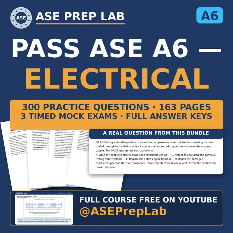
The complete ASE A6 course, free on YouTube: 34 video lessons built from ASE's published
A6 task list, with a printable workbook for every module. The ASE A6 exam itself is 60 questions (50 scored + 10 unscored) in 90 minutes.
Every A6 module workbook — follow-along worksheets matched to the free video lessons
The complete 300-question bank with full answer explanations
Three printable mock exams with full answer keys
One-time purchase · Digital files for personal study
Look inside the workbook
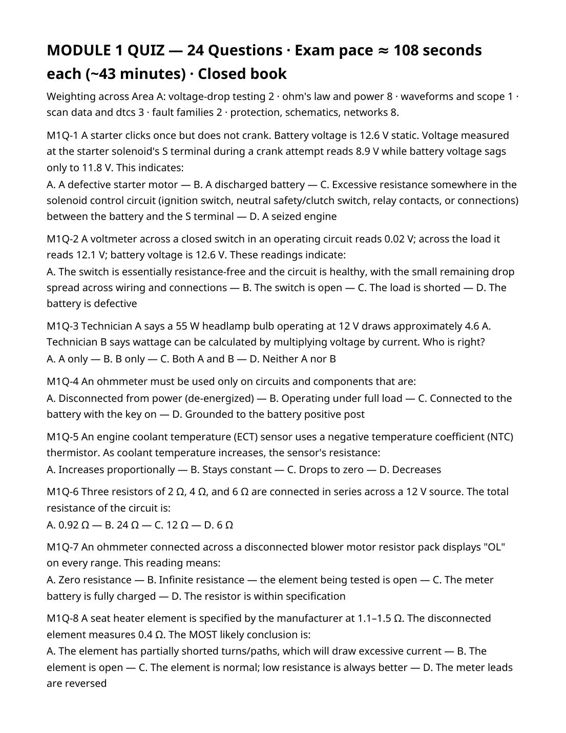
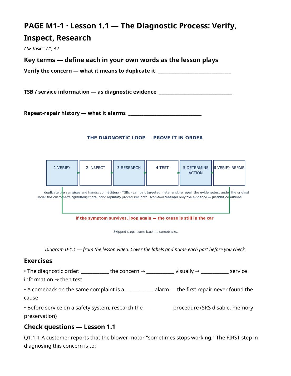
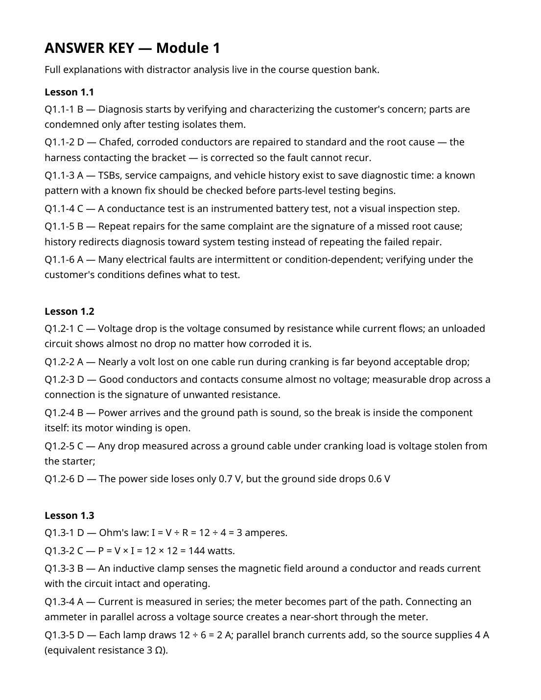
Actual pages from the ASE A6 Electrical/Electronic Systems Module 1 workbook — the same PDF you download after checkout. Every module follows this format: a follow-along worksheet for each lesson, lesson check questions, a timed module quiz, and a complete answer key with rationales.
Timed module quiz — Module 1 workbook, PDF page 20Follow-along worksheet — Lesson 1.1, Module 1 workbook, PDF page 2Answer key with rationales — Module 1 workbook, PDF page 25
Printable workbooks
Prefer to study on paper? Each module has a printable follow-along workbook with worksheets and practice questions
drawn from the same 300-question bank as the video course.
Buying one topic at a time? Each module below includes only that module\'s workbook and its questions. The complete pack above includes every module plus the Finals mock exams.
Seven questions from the ASE A6 question bank, spread across the modules. Pick your answer, then open the reveal
to check it and read the explanation.
Sample question 1 (QA-20, Module 1)
A voltmeter across a closed switch in an operating circuit reads 0.02 V; across the load it reads 12.1 V; battery voltage is 12.6 V. These readings indicate:
The switch is essentially resistance-free and the circuit is healthy, with the small remaining drop spread across wiring and connections
The switch is open
The load is shorted
The battery is defective
Show answer
Answer: A. Drops around a series circuit sum to source voltage; near-zero drop across the closed switch means it is passing current cleanly, and the load receives nearly all of the available voltage. Distractors: B — an open switch would show full source voltage across it. C — a shorted load would show near-zero volts and blown protection. D is unsupported by a 12.6 V static reading. Source: Task A3.
Sample question 2 (QA-59, Module 1)
A vehicle kills its battery overnight. With the key off and all modules given time to power down, the measured parasitic draw is 720 mA. The correct conclusion is:
This is normal for a modern vehicle
The battery must be replaced before any further testing
The draw will stop once the battery is fully charged
The draw is far above the typical manufacturer allowance (commonly on the order of 50 mA or less — always confirm the vehicle specification), so a circuit is staying powered or a module is not sleeping and must be isolated
Show answer
Answer: D. Three-quarters of an amp overnight will discharge any healthy battery; a draw of this size means something is awake that should be asleep. Distractors: A misstates normal key-off draw by more than tenfold. B condemns the victim, not the cause. C — charging does not switch off a stuck load. Source: Task A9.
Sample question 3 (QB-14, Module 2)
Technician A says an open-circuit voltage reading of 12.6 V proves a battery is good and needs no further testing. Technician B says open-circuit voltage shows state of charge only; a battery at full charge can still lack capacity, which requires a load or conductance test to judge. Who is right?
A only
B only
Both A and B
Neither A nor B
Show answer
Answer: B. A charged battery can still be a failed battery — voltage is the fuel gauge, not the engine. Capacity under load is the true verdict. Distractors: A-only and Both credit the most common battery-testing mistake in the trade. Neither denies B's correct distinction. Source: Tasks B3/B4.
Sample question 4 (QB-41, Module 2)
A fully charged battery and verified-good cables supply a starter that cranks the engine slowly while drawing current well above the manufacturer's specification. The MOST likely cause is:
A high-resistance battery cable
An open solenoid winding
A dragging/worn starter motor (worn bearings, shorted armature windings) or excessive engine mechanical drag — current is high because the motor is working against abnormal resistance to rotation
A weak ignition switch
Show answer
Answer: C. With supply proven good, excessive draw and slow cranking mean the load itself is at fault — the motor is laboring, electrically or mechanically. Distractors: A would limit current (and was verified good). B would stop operation entirely. D is in the control circuit, which does not set main-circuit current. Source: Task B10.
Sample question 5 (QC-16, Module 3)
An AC voltage (ripple) measurement at the battery with the engine running shows excessive AC content, and a scope shows one phase's humps missing from the ripple pattern. This confirms:
A healthy alternator
A rectifier diode (or stator) fault — the three-phase output is no longer being fully rectified into smooth DC
A bad battery cable only
Normal operation at high rpm
Show answer
Answer: B. Ripple is the alternator's fingerprint: uniform small ripple is normal; a missing or distorted hump pattern is a diode/stator confession. Distractors: A and D dismiss a defined fault signature. C — cables drop DC voltage under load; they do not reshape alternator ripple. Source: Task C4.
Sample question 6 (QD-19, Module 4)
The right turn signals flash at double speed while the left side flashes normally. The MOST likely cause is:
A failed flasher unit
A burned-out bulb (or open circuit) on the right side — the reduced load is the classic fast-flash bulb-out indication
Low system voltage
A shorted hazard switch
Show answer
Answer: B. Flash rate follows load: one side's missing bulb halves that side's current, and the flasher (thermal or module-logic) answers with hyperflash on that side only. Distractors: A would affect both sides. C slows or destabilizes flashing system-wide. D takes out hazard and turn functions together, not one side's rate. Source: Task D4.
Sample question 7 (QE-52, Module 5)
A heated seat comes on, gets far hotter than it should, then shuts off and will not restart until the vehicle is cycled off and on. The MOST likely fault is:
The seat element is open
The seat switch is stuck
The seat temperature sensor (thermistor) is reading falsely low, so the module keeps driving the element until over-temperature protection shuts the system down
The battery is overcharged
Show answer
Answer: C. Closed-loop heat needs honest feedback; a thermistor lying about temperature makes the module cook the seat and trip its own safety. Distractors: A produces no heat at all. B would show as a switch input fault and typically one behavior, not overheat-then-lockout. D doesn't target one seat's regulation. Source: Task E5.
All 300 questions for ASE A6 — with full answer keys — are in the printable workbooks above, and every one is
worked through in the free video lessons.
ASE A6 Electrical/Electronic SystemsComplete bundle $24.99Buy direct — $24.99
Want more free practice first? Take the ASE A6 practice test — 15 free questions with answers and explanations.
Taking the test soon? Read the ASE A6 exam guide — format, task areas, registration windows and a study plan.
 ASE Prep Lab